Drawing a circle using the vector drawing tools

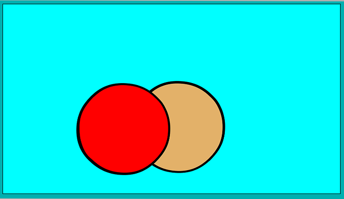
Because of the way that Bezier Curves are defined in Pencil2D, a circle cannot be drawn as a single shape. Instead it is composed of two identical drawings which are reflections about the X axis.

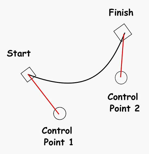
A Bezier Curve segment is defined as a start and end points, together with 2 control points, as shown below.

The end segments of a Pencil2D Bezier Curve tend towards a straight line and in version 0.6.6 there is not connect command. Although in version 0.7 there is, there are still some problems drawing a smooth vector curve. Hence as mentioned at the start two curves are used.

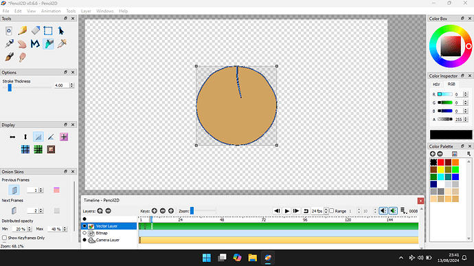
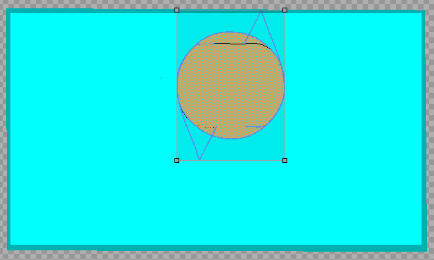
The circle itself is drawn uning colour 24, which is defined a bright pink with an alpha value of zero. This has the effect of making it invisable. Although during some editing operations is shows as a thin black line, as shown below. It’s shows better when you use selection tool applied to 1 of the frames of Vector_Circle.pclx (28.0 KB).

Vector_Circle

Once drawn these can be selected as a single entity and manipulated together as a single shape, including moving and compressing, with a circle rotation doesn’t have any practical application.

But once the circular ball has been compressed the rotation could be applied usefully if the ball bounces off a rough surface.

Vector_Circle

The above image however shows the ball bouncing off a flat surface.

The Pencil2D file used in this project is Vector_Circle.pclx (28.0 KB)

One advantage of using vector drawings is that the Pencil2D files produced are smaller than for Bitmap drawings.

It’s important to state that this project was done using Pencil2D only and no external software was used!

1 Like

Excellent work Mary, your efforts prove the theorem that you can get too close to a problem, that you cannot see the wood for the trees!

My take is that i’m a traditional animator, that means that I like to have a black line around my drawings and hence my take on your animation.

Balls

I don’t use the line facility within Pencil2D because the lines and fills are drawn on screen in the wrong order. The fills are displayed on the correct order from the bottom to the top of the display stack. Then the lines are displayed in the same fashioned.

What is required is that the bottom fill and then the bottom line needs to be displayed and then so on to the top of the image stack.

The image stack is a simple concept, the background, then the mid ground and then the foreground objects are displayed in that order. Thus is a mid ground objects is in front of a background object, the background drawing that’s behind is obscured by the mid ground object.

To understand what is happening and why, you can load Balls.pclx (39.6 KB) and examine frame 1 of the animation in the file called 001.002.vec file.

The palette is the standard pallet, as defined when you start up Pencil2D with the addition of colour 24 which is a Pink colour with an Alpha value of zero. Colour 23 is the lightest brown in the palette and black colour 0.

Thus the 2 black shapes are laid down first. followed by the the 2 light brown shapes. the shapes are defined in the first 4 blocks of XML code and then the next 4 define the fills. Both of these blocks of 4 the shapes are in the same order in the XML coding!

The use of two fills not only allows the image placing to work, but also allows the line thickness to be varied around the drawn objects.

These 2 shapes the red and light brown circles can be moved, resized etc. independently of each other. If you wanted to do the same in bitmapped drawings, you’d require to use 2 layers.

1 Like

How we can approach the vector tools in Pencil2D is either we say that:-

They are unusable and that we can’t use them until they are fixted.

Or we can experiment with them to see what can be achieved using them.

If we look at the work of Mary Smith, Stop Motion Vector, we see that they have developed workflow’s that acheive excellent results.

If we build on these techniques we can acheive excellence in animation!

I’m definitely not saying that the Pencil2D animators that use bitmapped drawings are wrong. I look at their work with admiration. I find inspiration in their work. I use vectors as a drawing media because vector animation techniques suites my skill set.

I am not a purist, I do use bitmapped images in animation projects, when I feel that they are the best technique to acheive the desired result.

We do live in an environment where most output & input devices to computers work using bitmapped formatted information.

This has been made possible due to the availability of low cost memory. Modern computer screens are memory mapped. This means that a number of bytes is used to store the information of each pixel, that makes up the displayed image.

We still however use vector based images where the same image is required at a range of sizes. An example is an organisation’s logo. This may be required to be printed on product packaging, shop fronts, the sides of it’s vehicles, websites and printed correspondence.

Using vector graphics allows for the same image being output in full colour and black and white for other applications.

Since the above logo is vector based it is easy to change it colour and resolution, this controls how large the image is when reproduced.

A bitmapped version would have feathered edges, to make them appear smoother, these are pixels of different shades proportional to the proportions of the pixel used in a smooth curve.

Feathering is applied to the edges of a vector image, but it’s applied at the point where the image is displayed, rather than at the drawing stage.

When it comes to problems in the application of our artistic or other skill sets, there are 2 approaches. These are

Find a solution to the problems encountered.

or

Complain that the techniques and or materials don’t allow my artistic expression.

I an personally in the first category, like many animation artists who worked for Disney making traditional cel based animation, like Hanna Barbera.

Similarly other artists, such as Salvador Dali or Vincent van Gogh, didn’t let problems stop them developing new techniques.

As an aside, I wonder how many users realise that when adding text to their work, when using a bitmapped graphics package, that the text is stored as a vector image. That way a single definition of each character can be used to generate any size if characters in the users work.

The reason for the inventing of vector graphics, was the high cost of memory pre 2000’s. 1980’s computers like the VIC 20 and the ZX Spectrum were early adopters of bitmapped lettering, but initially only a standard font in a single size.

I have drawn a circle in my first posting on this subject. I choose the circle because it is a difficult shape to draw using the Pencil2D vector toolset. On my first attempt I used 2 identical shapes, the second shaped was reflected about the X axis.

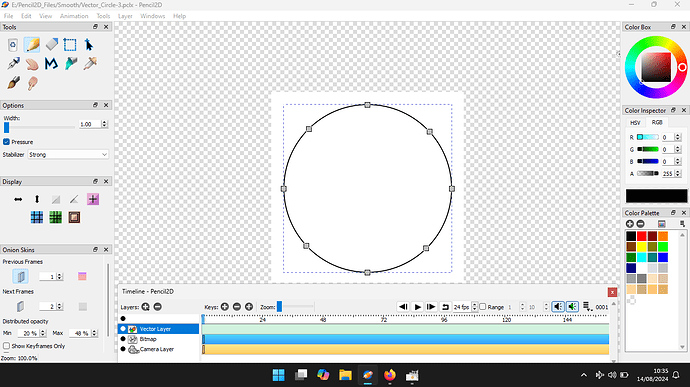
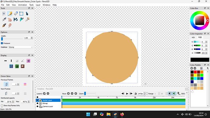
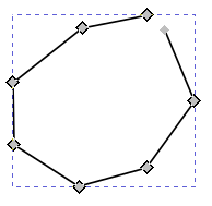
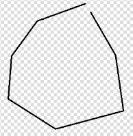
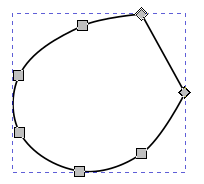
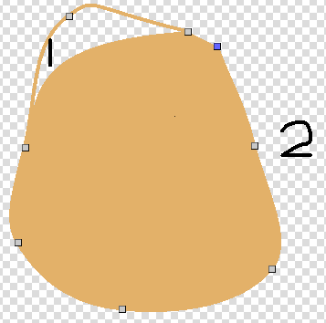
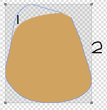
I have since attempted to draw a circle, using the vector tools as a single shape. Below is this attempt. Firstly I drew the line, shown in black and then filled the resulting shape.

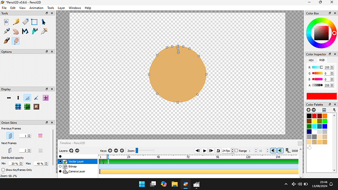
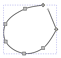
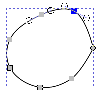
Then I hid the line, by colouring it with and invisible colour and then highlighted the control points along it.

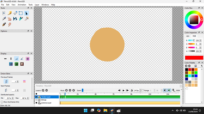
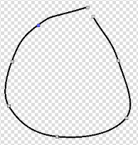
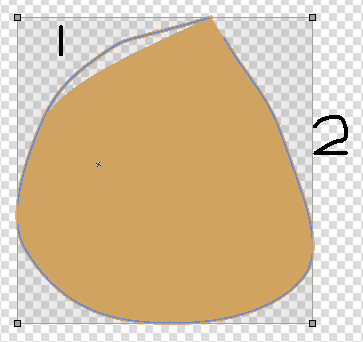
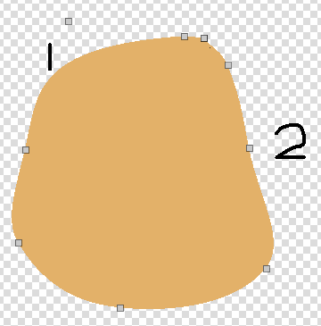
Finally I have presented the finished circle with the line hidden and coloured in.

This progress has been achieved as my knowledge of the Bezier curve equation and how it is used by SVG software. I have been reading the Behind the Scenes: Pencil2D New Icon Set.

I then loaded and read the section of the SGV website, particularly the section on paths, that the technical name, for lines the lines that describe a shape and we can then fill to produce a shape in vector graphics.

I think I understand why simply drawing the desired shape does not provide the results that are required. Using this insight I have been able to produce the final shape. There’s a little refinement required in my circle and the process required to draw it, but I feel that I’m making progress!

You may think that I never use bitmapped images, but if you examine the last illustration in my previous post, you’ll see that the project has a bitmap layer.

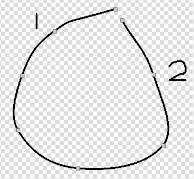
The image above shows what the image is, it was used as a guide to draw the vector curves, to produce the circle path.

I drew this line using the Vector tools within Inkscape. I used the circle tool, then converted it to a path. Because I felt this wasn’t sufficient points, I then added an extra point between each of the 4 points. This was then exported as a.PNG file and then imported it into the Pencil2D bitmap layer.

The illustration shows the finished curve, filled and then the path, the line in other words coloured with a colour with an Alpha value of zero. I call this colour Invisible.

So as you can see I take a pragmatic position, when it comes to using bitmap images. If their useful I use them.

Stage 1 of drawing a shape in both Inscape and Pencil2D produces simular paths.

Inscape-1 Pencil2D-1B

When smoothing is applied to the paths, without joining the ends together, the result too is simular.

Inscape-2 Pencil2D-2

At this point I joined the ends of the path, to make the path contigious.

Inscape-3

As shown below, the Inkscape image is as we desire a smooth path, but the Pencil2D image requires more work to acheive the desired shape.

Inscape-4 Pencil2D-4

Pencil2D-5

When the Pencil2D path is filled, there is a gap between the line and the fill. At present this cannot not filled, so my next process is to hide the path.

Pencil2D-6

This is done by selected it and the changing it’s colour to what I call Invisible. This is a colour that I don’t often use, with it’s Alpha value set to zero.

Pencil2D-7

To get a more flowing shape I have used point 1 to pull the segment, of which it is the mid point out. There is a limit as to how much pull-out can be applied. This is limited by the Smoothing Coefficient, set in the Preferences.

I then added an extra point between the join point and point 2 and used this to pull the path out to the desired shape.

Pencil2D-8

Please note that these techniques do not work when drawing a circle, due to the symmetrical geometry.

A recent Nightly Build has added a path join function, which like the SVG convention and as implemented in Inkscape joins the 2 ends of the path with a straight line. As yet there is no attempt to apply the Smoothing Coefficient over the entire path.

For this exploration of how Pencil2D vector graphic work, I started off my drawing a target shape using Inkscape and then loading it into bitmap layer within Pencil2D.
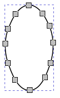
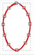
Shape_Inkscape Shape-1

Next using the Polyline too I overdrew the shape. I started with the top control point which are marked by squares filled with grey colour.
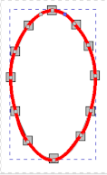
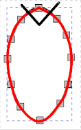
Shape-2 Shape-3

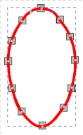
Next I used the Pencil2D Smudge Tool to move the control point, to the right of the top grey rectangle until it was over the control point square. With this simple shape I Realised that all i needed to do was add 2 extra control points. I drew the black line and as a result I added the required points.
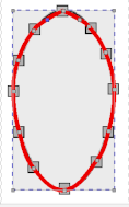
Shape-4 Shape-5

All I then had to do was move these point to achieve the desired line. That’s the process to perform the task by trial and error method, now let us examine the .VEC file to work out how to possibly automate the process.

Firstly let us examine the relivent part of the original .SVG file. Please note that I have reformatted the data so we can examine the relationship between the .SVG and the Pencil2D .VEC file.

SVG File Listing
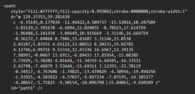
SVG_List-2

Pencil2D VEC LIsting

The way that i have reformatted the .SVG information. The first line of the .SVG coreesponds with the first line of the Pencil2D .VEC file. This pattern continues until the last line of the .SVG, just before the id=“path-1” />. The line before this ends with z", this indicates that at this point the path connects with the initial point, in the second line d="m 129.253, 59.281438, these are the start coodinates of the path.

Each line after the second line, in the reformatted file contains 6 sets of X and Y coordinates.

The first pair are the X and Y coordinates of Control Point 1, followed by the X and Y for Control Point 2 and then the X and Y coordinates of finish of the path segment. This is also the start of the next segment of the path.

The final line of the Pencil2D .VEC file replaces the z" at the end of the final line of the .SVG file, with the Control Point Values and the start point of the path.

We need to set the final X and Y of the path to the start X and Y coordinates. The the X part od Control Point 1 needs to be the same as the X coodinate of the previous point and the X coordinate of Control Point needs to agree with the X coordonate of the path Finish point.

The Y part of Control Point 1 is the Y coordinate of the Previous point - minus 4. The Y coordinate of Control Point 2 is the same value. This value might sound arbitrary, but if its wrong the plot point can be adjusted using the Smudge Tool. What’s most important is that the point is not on top of the Previous point, because Pencil2D will lock the two points together.

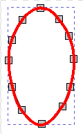
The shape below is the final shape, which is produced by the modified version of the Pencil2D .VEC file.
Shape-6

This is an initial attempt to automate the process, it will require some refinement. The circle case is the most difficult curve type because of the way that Pencil2D Bezier Curves work and the case we have just examined is significantly easier case.

The case that Mary tackled before this entry is what can be considered the ‘General Case’.

If the curve at the point of joining the two ends of the path is a larger radius, then it is harder to smooth the join, by moving control points within Pencil2D.

For examples covered in this posting, the radius of the join area is smaller and thus the join can be manipulated using the control points within Pencil2D.

In most cases the animator can define the shapes required to draw the characters and props using the Pencil2D vector tools.

In some circumstances a little ingenuity is required to acheive good results. But with practice you can draw any shape that you require.

If a character requires, say the head to move, in general the face is in front of the body. The animator can draw the body shape with the join under where the face will hide it.

The circle, for my bouncing ball animation is the most exacting situation.

Stop Motion has been working to convert an .SVG image into a .VEC one, but this has as yet not been fully successful.

I think that vising vectors in Pencil2D isn’t straight forward as using bitmapped images, but it is possible even for production jobs, those are projects done for clients.

Nothing in life is ever guaranteed to be easy and trouble free and those who expect this are not being truthful with themselves or others.

I’ve found during my course, in graphic design, which includes animation, that you are rewarded for effort, in pushing your skills to their limits.

Also the new version of Pencil2D V 0.7 has a line, called a path in vector notation, join command by right clicking the mouse and pressing the control key at the same time.

I do of course realise that the computer screen and printers are bitmapped devices. With vector images they are converted at the last moment.