If we choose vector, it could be hard coded into the source files. No need to import it. It would be a datafile.h
Pencil2d vector graphics are 1st generation vector graphics. Other vector packages are 2nd or even 3rd generation. So to import vector graphics conversion software would be required.
Since all vector formats are save in XML format, the conversion is a text processing problem, but you do require to understand how the differences between standard SVG files and Pencil2d VEC files.
A good place to start would be a shape, with no straight lines, just a series if curves.
I have put some though into how this would be possible. I think that we need to start from a simple vector file and then as we gain more e experience, tackle more complex files.
We’re talking at cross purposes, but I and my line manager in work have explored how to convert SVG files into VEC files.
We have written synthetic VEC files, which have properly been displayed by Pencil2D.
We examined the possible problems with VEC files, one of these is the first and last segment is always a straight line.
We’ve cracked how to draw a shape composed of only straight lines, like a square.
I’m convinced that the conversion is possible and that it offers a way to extend the applications of vectors in Pencil2D.
We have a set of ‘work arounds’ and we have used Pencil2D, to produce production jobs, for clients.
Pencil2d’s power is it simplicity, packages like Adobe Animator, are often too clever, for their own good!
1 Like
I am sure there is a possible way. Either conversion or self drawn graphics. I have made a very crude example. I am no artist.
The example was made with inkscape btw. Every object is able to scale up or down and you can move them around on the canvas, before you put it permanently on the canvas. In Inkscape you stamp it with the space bar. In the internet, on openclipart.org are many free grapics, we could use for free. Public Domain.
Proposal to build a stand alone utility to convert Plain SGV files into VEC files
Using Pencil2D as opposed to using Adobe Animator or Moho Studio is because I prefer the simple, to user interface. The workflow suites artistic process.
Background to my use of Pencil2D
At college I studied traditional animation, hand drawing on paper and then copying the images using Indian ink onto cells, theses were modern plastic, not the celluloid ones.
When I started working, computers had started to take over. Most of my work, was based on vector drawing technology. The first package used 640 by 480 pixels, although this rapidly became 720p as standard.
When I started to use Pencil2D I naturally gravitated to the vector drawing and manipulation tools. I find them very effective. I have a mindset of where problems occur, that I work out workarounds, these enable me to carry out tasks, that Pencil2D cannot do.
Once you have learned how to do them, they become a quick and reliable way to achieve the required results. I have used Pencil2D, using the vector tools, to produce Production animations, for a variety of clients, over the last 3 years.
Currently I use Inkscape or Adobe Illustrator, to do the visual experimentation involved in character design, once the process is complete, I export the drawings in .PNG format and then overdraw them using the vector tools with Pencil2D.
Therefore having a conversion utility would make my workflow easier and quicker, so that why I’ve done the experiments that I have done and that’s why I am going to write a conversion utility. I will be writing it in Python, because I am familiar with that programming language.
I am prepared to make the utility available to other, who might find it useful. I feel that I will fill a gap in the vector tools that Pencil2D provides.
I never work with large projects, as a single project file, using Pencil2D. I therefore divide the project into shots or scenes and I work on each of these separately, thus keeping the files smaller. Therefore I have never exceeded the 64 sound file limit, within Penci2D.
![]()
Building a stand alone utility to convert Plain SGV files into VEC files
The reason for this approach is that it simplifies the process, the output of the utility, would be in the form of a synthetic .PCLX file. This could then be imported into Pencil2D and or layers from it could be imported into a Pencil2D project. Since the software would be free standing, it could be written in Python, which I have more experience in using, rather than C++, which I am very rusty in using.
Exploration Already Done
I have converted several simple .SVG files manually using Notepad, on a PC computer. I have also written several VEC files, from first principles, Both of the above have been able to be imported, as part of a synthetic .PCLX file. I have used conversion utilities built into Adobe Animator and Moho Studio. Neither of these conversions, was completely error free, but a few simple tweaks and the results were acceptable.
How Vector File Formats Work
The parts of the image are stored in a stack. Most of you will be familiar with a stack of books on a table. The top book cover is totally visible, but the one below may be only partially viable. Lets examine how this applies to a graphic image in .VEC format.

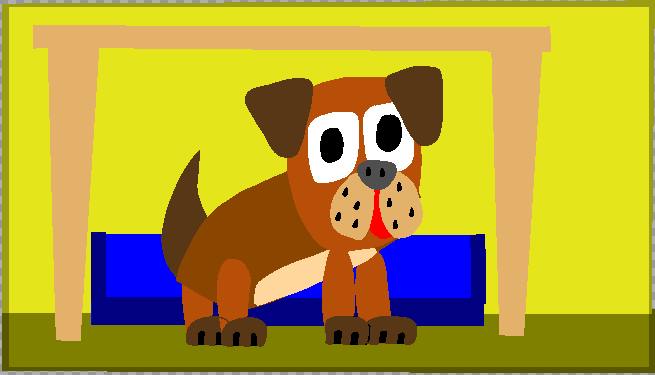
This character is called Smiffy and is composed of five logical layers, these are from bottom of the layer stack upwards, Tail, Body including the tummy patch, Head, Ears and Legs and Paws. In a pencil2D project all of these shapes exist on a single Pencil2D layer. But these shapes can be individually manipulated. Sub parts of the Face, Body and Legs and Paws are also able to be manipulated within Pencil2D.
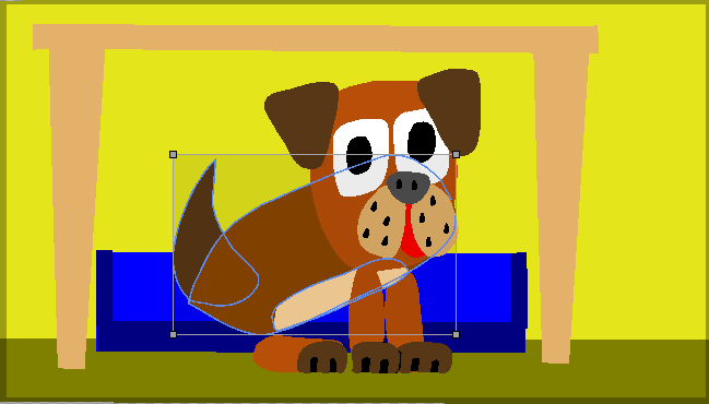
Moving, Resizing and Rotating parts of a characters within Pencil2D
Now let’s go into more detail, of the process of doing stop motion animation using vector images.
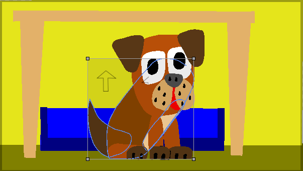
This character is called Smiffy and is composed of five logical layers, these are from bottom of the layer stack upwards, Tail, Body including the tummy patch, Head, Ears and Legs and Paws. In a pencil2D project all of these shapes exist on a single Pencil2D layer. But these shapes can be individually manipulated. Sub parts of the Face, Body and Legs and Paws are also able to be manipulated within Pencil2D.
Moving, Resizing and Rotating parts of a characters within Pencil2D
Now let’s go into more detail, of the process of doing stop motion animation using vector images.
In the above pictures, these show the movement of the body of Smiffy into the required position. This rotation is about the centre point of the selection.
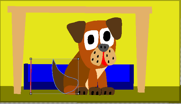
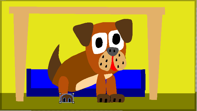
We now need to move the selection into the required position, by moving it slightly to the left
When you have finished using a selection, the selection can be de-activated by using the smudge tool, located outside the selection and a left mouse click.
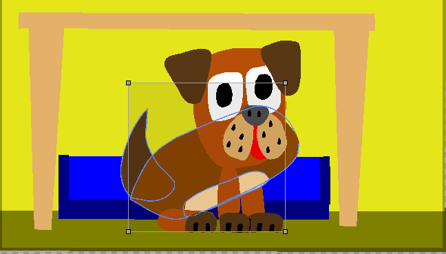
Then we need to move the back paw, closest to the camera view into the required position. This is done in two stages, first we move and rotate the leg and then the paw. With the paw we need to ensure that the shadow behind is selected with the paw, before we move it.
The above view is what we want to achieve, but this cannot be done in a single operation. First we make a duplicate using the duplicate button, on the top of the timeline.
Then we select and delete all parts except the required hind paw and leg, on the new copy of smiffy. Using the onion skin feature, set to 1 frame we can see both the frame with the hind leg only and the frame containing, the rest of Smithy.
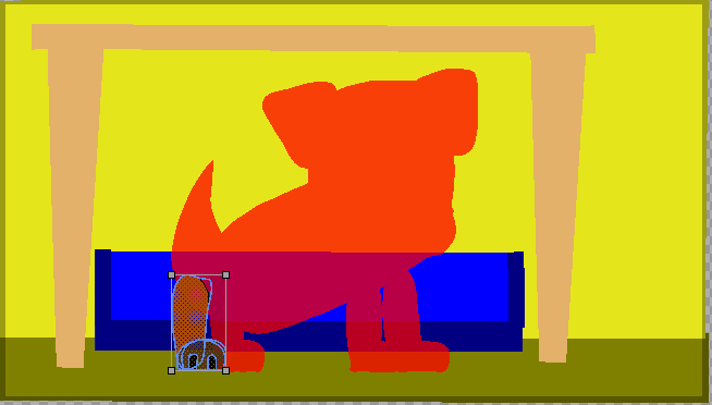
Thus we can adjust the hind leg. We can then copy the first of these 2 frames on top of the second and then when we’re sure that we are happy with the composite frame, delete the first of these frames, the one without the second hind leg.
At this point I realise that both hind legs, were not quite in the required position. They can be both selected and move together. This is one of the advantages of working with vector images, in Pencil2D.
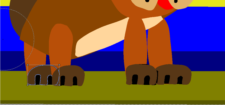
At this point I realised that there is an unwanted line around the hind paw, which is partially behind Smiffy’s body. This is caused by a slight bug in the vector graphics of Pencil2D.
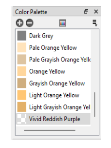
It is easily fixed, within the colour pallet of Smiffy-Start.pclx (571.6 KB) there is a colour called Invisible, to hide the line you simply select it and using the colour Invisible you re-colour it and it is now invisible.
All lines are added above all the fill layers, instead of fill and line, and then fill and line etc. This is easily overcome if you want to draw traditional lined characters, in Pencil2D.
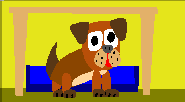
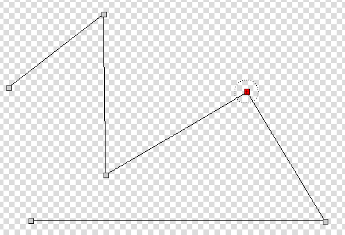
The illustration above is the final drawing, with the hind legs in the desired position. The previous view has a dotted circle, this is caused by the use of the smudge tool. This is used to cancel the selection of vector drawing elements.
Re-ordering the drawing components within Pencil2D
This process within Pencil2D, is a knife and fork process. To go back to the image of Smiffy below. If I wanted to move her Ears from in front to behind her head, I have to duplicate the image. Then delete all parts of her except the Ears on one copy and the Ears on the other copy. Then copy the version, with the missing ears, over the version with Just the Ears.
Using a package, like Inkscape, I would select the Ears and then simply used the lower layer tool and the job would be complete.
The use of the conversion Utility
This would allow the preparation of images to be done, using packages such as Inkscape, which went complete, these images could be converted in ,VEC format and then via the mechanism of synthetic .PCLX files could then be imported into Pencil2D.
Using the utility by Pencil2D users
When the project reached a usable state, I propose that the utility would be made available to Pencil2D users.
I think that promoting the use of Pencil2D’s vector tools would widen the market, as far as the package is concerned. Although many feel that the vector tools are not complete, they are never the less a very impressive set of tools. Could they be improve, the answer is of course yes, but they are very usable in their current state.
What puts off their use, by animators more use to using bitmapped tools, is that the tools work differently. To work on a shape, to fill it for example, you must first select it. To use the control points, the animator must first activate them, by clicking on the outline with the Smudge Tool.
Like when using the bitmapped tools, there is sometimes a slight lag, between an action and seeing the result on screen. There are some situations, where the user zooms in, where the tool appear to fail. This is particularly the case with the line tool. Don’t be put off, You may appear to have a very wavy line, but when you double click to terminate the drawing process, you’ll see you have drawn a set of straight line. Persevere and you’ll be rewarded!
I think, therefore I am, is a statement in pholosophy. It means that because I can think, that I exist as a being in the universe.
Thinking and the associated experimentation is an important way in which art has progressed from cave paintings to the electronic based art of today, including animation in Pencil2D.
When I was at art college, wed did several assignments using state of the art computer graphics, Microsoft Paint. On my own computer, I then installed Corel Draw, a vector based drawing package.
Most of my illustration projects were then drawn using Corel Draw,including my final year project.
I don’t have any hangups about using bitmapped software, I just have a preference to draw using vectors. This is because is suits my drawing style. If you prefer using bitmapped techniques, good luck and I hope you canwork towards acheiving your artistic dreams.
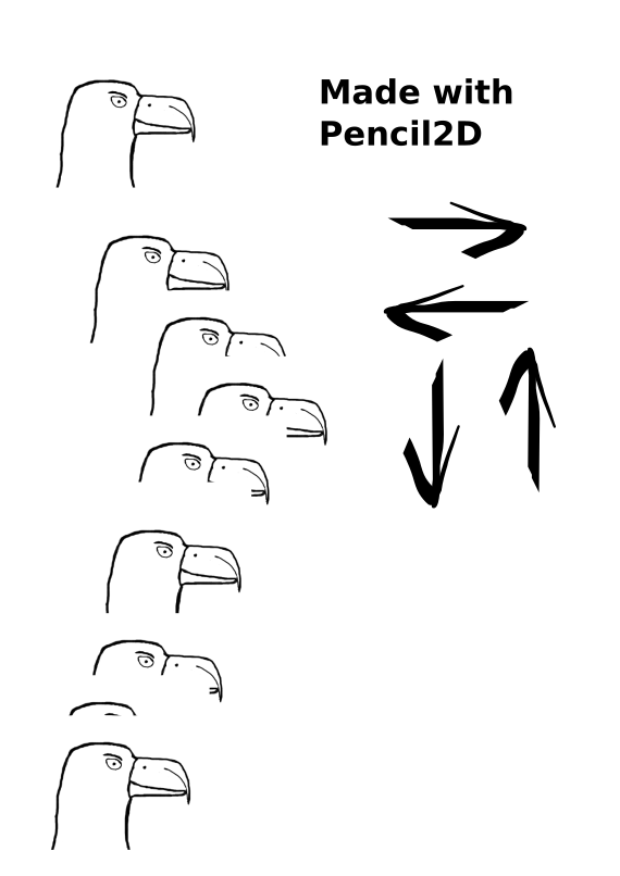
The animation below shows the the basic steps in going from a .png format into .vec. This method is what we call a ‘Knife and fork’ method. This means that it works, but it’s not the most elegant method.
It is generated from the VEC_Illustrations-2.pclx (89.2 KB) and it steps through the process. It is important that we understand the convertion process before we attempt to automate the process.
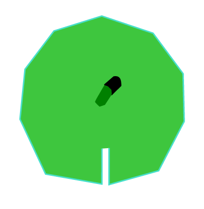
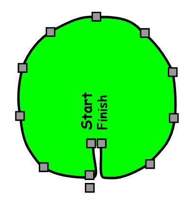
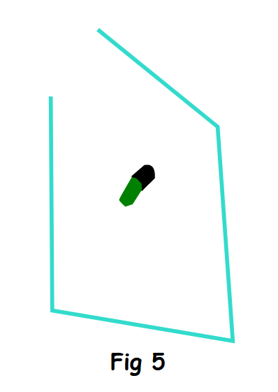
We start with a guide image, this is a .png image. WE then draw a line, or rather a series of straight lines arround the perimeter. For the time being ignore the extra two lines at the start and finish ofthe shape.
When we click thwe shape with the Smudge Tool the shape is converted into a curved line, the exact shape is controlled by the vector curve smoothing setting in the Preferences.
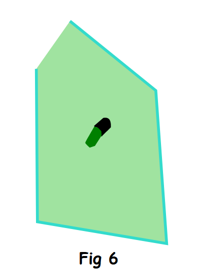
At this point this is only an outline and in order to fill it, we require to select it, using the selection tool. Once selected it’s colour becomes light blue.
Then we can fill it with our choosen colour. The line colour changes to the fill colour, with a think light blue line also. The latter indicated that the shape is selected. To remove the selection, we require to click on the area outside the shape, with the Smudge Tool selected.
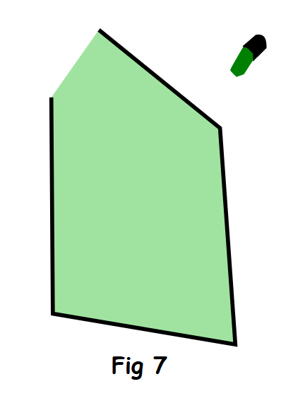
Next we need to hide the outline, the reasons for this might not be obvious, with a single shape, but when drawing a character like Smiffy, it would present a few problems.
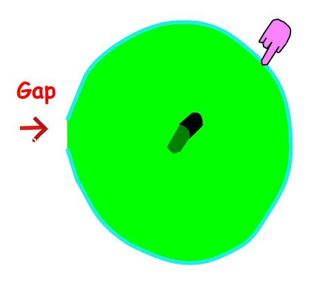
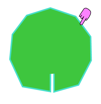
If we know using the Smudge tool, we click on the edge of the image, the control points will be displayed. Moving these around changes the shape of the vector image.
You will notice there is a single control point outside the shape, if we move this, we can partially close, the gap in the vector image. By then moving the left had control point, at the edge of the gap in the image, to on top of the right control point next to is, we can completely close the gap in the image.
The reason for making the outline invisiable, by using a colour in the pallet, created for this purpose, is that there is a very minor bug in Pencil2D vector graphics, that puts the fills in order that they appear in the image stack, and the draws the line in the order of the stack, but on top of the shapes.
I think that this problem could be solved, by putting a shape, then it’s line, starting from the bottom of the shape stack. Meaning that examining the stack, you would find shape, line, shape, line etc.
The process of hiding the lines is referred to as a Work Around, which enabled the user of Pencil2D to use the vector tools. Work Arounds and experimentation have been an essential set of techniques to art advancement throughout the history of art!
The advantage of using vector layers, from my experience is that, within Pencil2D, is that the animator can move, change the size of and rotate elements withion a drawing.
I thout you meant a tool to convert vectors from pencil into svg or something. Do you know the tool potrace? It can convert bitmap graphics into vectors. Inkscape has it as a tool.
FraFra
If you look at the first of the post, 2 posts ago, the title includes the word, ‘Proposal’, this should indicate that the project is in a very early stage of development!
I do mean, that our aim is to produce a utility to convert .svg files into .vec files. But for many I need to explain some background first.
This projects will take time, we’ve so far only done the basic research. Watch out for future progress.

Penny says "Please be patient, if you can’t you can use the, ‘knife & fork’ method, specified in the previous posting.
Meanwhile, to keep your interest, the animation below shows tge power of Pencil2D, to implement graphic Sheering.this despite there being no Graphic Sheer tool, within Pencil2D.
Incidently using vectors is an excellent way of producing text within Pencil2D, that can be animated, including shape Animation. The text in the above animation, is draw on a vector layer!
Hi. Just informing everyone following this thread. I’m going to separate the “conversion tool discussion” part into its own thread and put it on the same Ideas section because this conversation kind of derailed the original topic about potential promotion of Pencil2D.
In the future please try to stay on topic and if you want to talk about different things open a new thread. Thank you.
1 Like
HI Jose
I made a mistake, in my first posting, re this thread. Well I’m human after all, sorry.
The important difference between a bitmapped layer and a vector one, is it’s structure. The shapes are defined by an XML script, as is the functionality within main.xml, the master Pencil2D file.
XML files are text files, they are not formatted like word type files. But they are arranged in paragraphs
The graphic images are stored in a stack. The animation below, shows the principle of this, for the character Smiffy.
Differences between Bitmapped shapes and Vector ones
If you require to fill a vector shape, you must select it first. You can use the either vector selection tools, the dotted line tool allows multiple shapes to be selected together. You can use it to select a single shape.
You start from one edge, say the top right hand corner and pull the tool towards the bottom left corner of the desired shape. You can stop, when the shape outline has a light blue tinge. This indicate that it has been selected.
The other selection tool, shown below the dotted line tool, is designed to select a single shape at a time. You can however, select multiple shapes, by clicking on multiple shapes one after an other. If you make a selection mistake, you can undo it, by clicking on the Edit and Undo option on the top line menu.
But won’t the colour leak out, the answer is no, the result of the fill is shown below.
Click on the edge of the shape, deselects the shape and makes the outline return to the outline colour.
If you applied the paint pot as shown, with the shape below selected, the paint would not leak out of the gap. The edge will be a straight line, between the two ends of the line.
If you did the same with a bitmapped image, with a gap in the line, the ink fill would of course leak out and fill the entire drawing area.
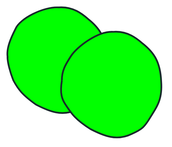
Why do I keep hiding the shape outline, it’s because if you place two or more shapes on top of each other, with the outline visible, the resultant image is like the one shown below.
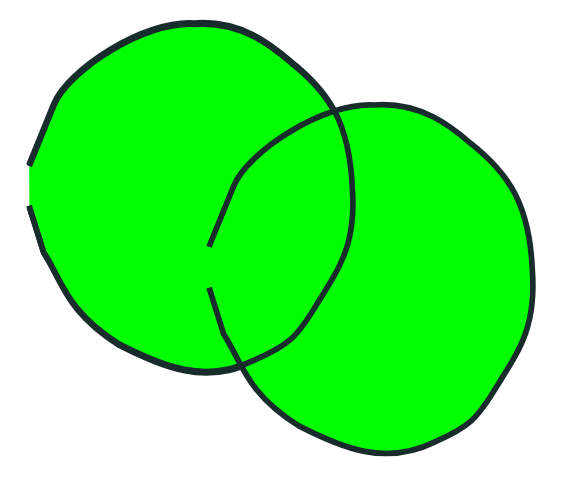
If what you desire is the image, like the one shown below, then you currently require to use the technique, with a second shape, coloured the desired line colour, positioned below the fill coloured shape.
The first instance is caused, by a minor problem with the Pencil2D code and the way the image is drawn on screen. The way the information is stored in the .VEC file is not the problem.
Choosing shapes to carry out Vector Operations
The general procedure is to select a shape or shapes to be worked on, carry out the desired operations and the freeze the shapes, by using the Smudge Tool, and clicking outside the selection.
The exception is the edit control points reset the selection, by click outside the shape, with the selection tool shown below. Then reselect the shape and then position the paint bucket outside the shape, with the desired colour selected.


The line colour selected will then be applied.
Initial Method to draw vector images, using Pencil2D
The Polyline tool, in Pencil2D, appears to draw a series of straight lines. You can draw a sequence of these lines, that approximate the desired shape. But when you attempt to adjust the shape, by moving control points, you discover that you have drawn a series of curves.
By a process of trial and error, it was discovered that, it was the best option, to select and fill the shape drawn, before attempting to move control points.
There is no join tool, or method provided in the Pencil2D toolkit. Therefore initially found that drawing a smooth outline to the desired shape, was very difficult or impossible.
If you attempt to draw a circle, using the Polyline tool. Thus all that can be done, is to place the last control point on top of the first. The smoothing co-efficient only acts between the 2nd control point and the 2nd to last control point.
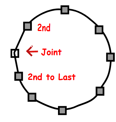
The first and last segments, tend towards a straight lines, because the smoothing co-efficient do not fully act on these segments.
Drawing curves, using Pencil2D vector tools
Next we will examine the process of drawing a circular shape, using the vector tool within Pencil2D.
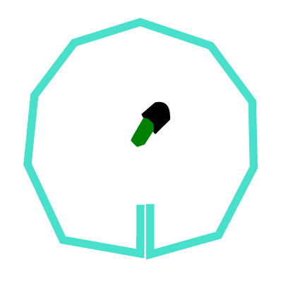
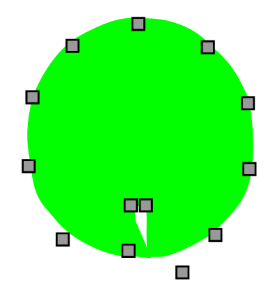
The initial stage towards drawing a smooth curve is to draw a series of lines, that look straight, until they are touched by the Smudge Tool, at which point they become a series of curves as shown below.
It might not be apparent, why the tails, which point towards the centre of the shape. The function of these will be come more apparent, when looking at the next illustration below.
It might seem counter intuitive, to fill the shape, before we adjust the shape, but this works best when using Pencil2D vector tools.
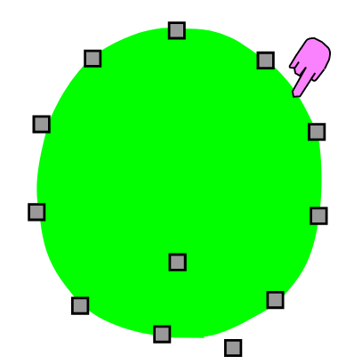
Now the shape is filled, using the desired colour, the next stage is to modify the shape, to meet out requirements.
The next stage is to convert the shape, to a series of curves, this is done using the Smudge Tool and clicking on the selected shape outer line.
Now we can start to adjust the shape, to meet our requirements.
There is a problem, when using Pencil2D vector graphics, in that the line around a shape is visible through, a shape on a layer above it in the vector stack. The solution is to place a copy of the shape, coloured the line colour, underneath the shape. This is because there is a minor bug, within Pencil2Din which the lines are placed on top of the shapes.
There is an advantage, in that the line width can vary around the shape. Provision for this has been designed into the .VEC file format, but has not been implemented in the code.
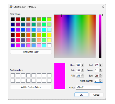
The initial step in this process, is to hide the existing line. If we delete it, then the shape will disappear, because the line is the container for the colour. But we can die it.
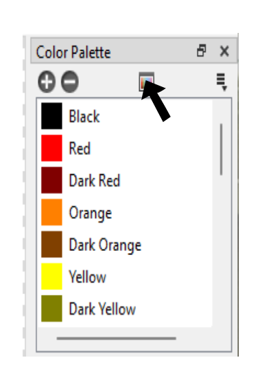
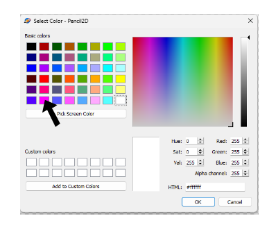
Then set the alpha channel to 0, this will create a new colour in the pallette. The next step is to change the name generated, by Pencil2D to a name that’s meaningful to you, the animator. I usually use the name Invisible, for this colour.
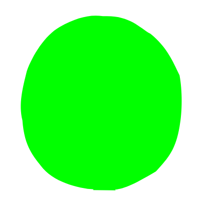
The image as shown below, is the same shape, as shown previously, but the line around it is now invisible.
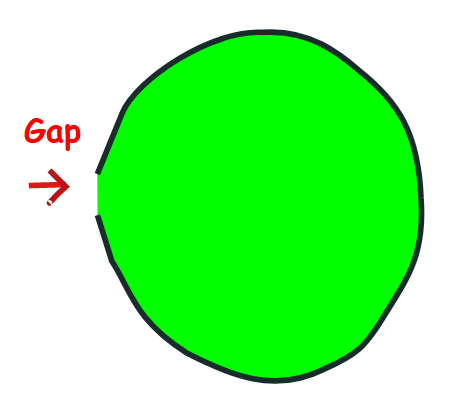
This leaves a slight gap in the shape and can be filled by moving the left inside control point over the right one.
The circular shape is now complete, not that one of the control points is outside the shape. This is as the result of the way that line segments are produced, by the Pencil2D software. If you hand code an .VEC file, using a text editor, like Notepad, this isn’t the case.
The shape is displayed on screen, complete.
If you require your shape to have an outline, you make a copy, colour it your required outline colour, enlarge it slightly and copy the original shape on top of it, to get the image shown below.
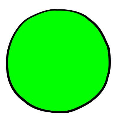
Why not just use the outline? There are situations where the outline will not follow the filled shape. This technique also has the advantage, that the line width can be varied, for visual effect. Although this is allowed for in the specification of the .VEC file definition, it isn’t yet implemented in the Pencil2D code.
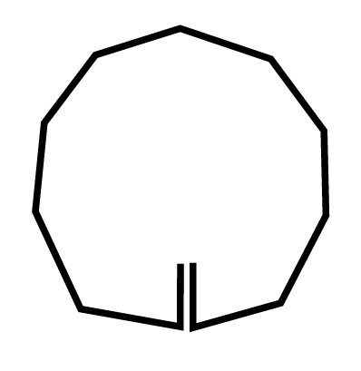
When using the .VEC tools, there is no join tool, as there is in packages, like Inkscape or Adobe Illustrator. We can only place the start point, on top of the start point of the line.
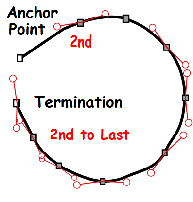
The Anchor point, is different, to the other points on the curve, in that is has to control point attached to it. In terms of the .VEC file, the termination point can be composed of two points placed on top of each other. This is generated because to terminate the Polyline input, a double click is required. These points, do have control points attached, unlike the Anchor point.
In Pencil2D the control points exist, in the .VEC file, but are not accessible from Pencil2D. The translation from the series of straight lines, into a curve is accomplished, using the Smoothing co-efficient.
The Smoothing co-efficient is not applied to the first segment, between the Anchor point and the 2nd control point or between the 2nd to last points. Using the inbuilt tools, within Pencil2D, you the animator has little control over the shape of these segments. When we examined the .VEC files, this fact gave us the first indication that having two points, with the same values, on two successive control points would force, a straight line to be drawn on screen. This proved a very useful ‘work around’ when we required a shape that required straight line.
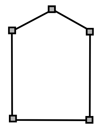
Without the ability to force a straight line in Pencil2D drawing a shape, like shown above would be impossible. Going back to a more general case of a combination of straight lines and curves. You can, of course adjust the control points, of a shape drawn, in Pencil2D, using the Smudge Tool.
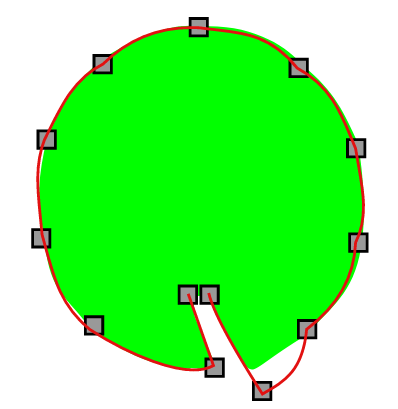
The above situation often occurs, when drawing a shape using Pencil2D vector tools. There is a gap between the outline of the shape and the applied fill. This is one of the reason, that the outline sometimes has to be hidden and a copy of the shape, coloured the outline colour has to be used to give an outline effect, when using Pencil2D vector tools. The outline colour shape has to be under the fill colour shape of course.
The control points of the fill shape, have to be adjusted to achieve the desired shape tool.
Using the two shape, within Pencil2D also allows the user to achieve the correct overlapping of two or more shapes.
As I have already pointed out, to fill a vector shape, you are required to select it, fill it and then deselect it after you have finished your editing and before proceeding to edit another shape.
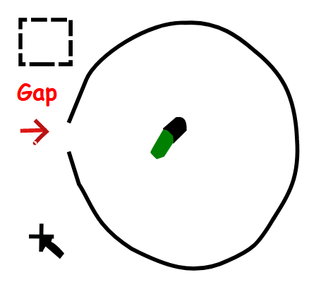
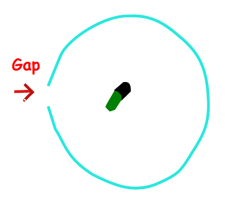
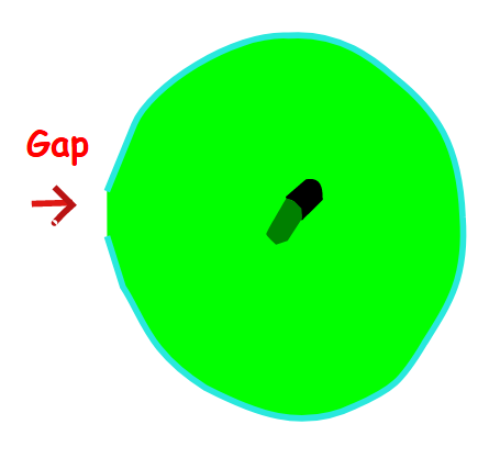
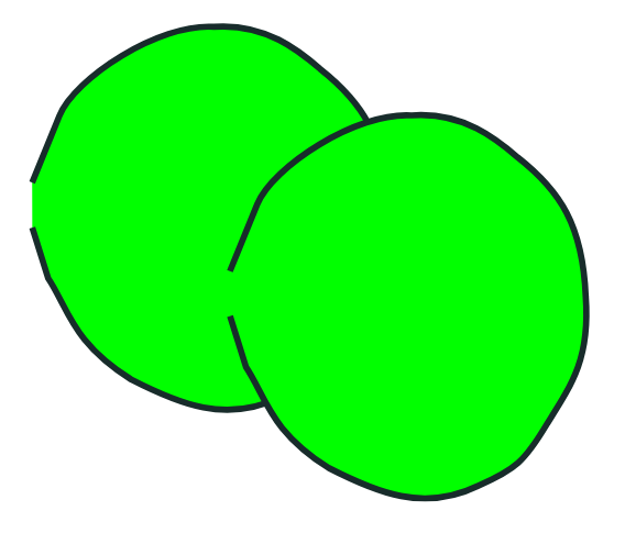
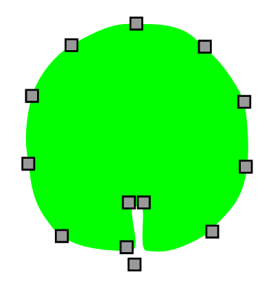
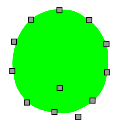
An interesting fact about the way human, and other mammals, see their world, is that a shape does not require to be closed, for us to identify the shape. This is an application of Gestalt Psychology.
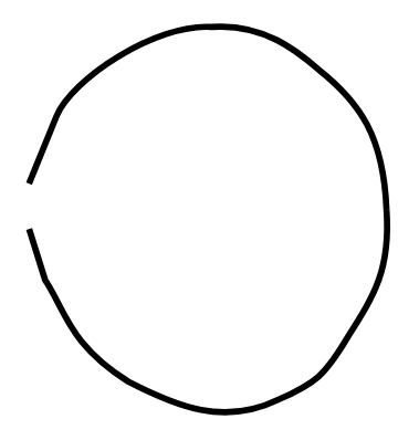
Humans presented with the above shape, for a very short period of time and asked what shape they had been shown, would identify it as a circle. This despite the fact it is not continuous and not a perfect circular shape. This is due to the way that we process visual information.
Persistence of vision is important, without it television, film and in particular Animation wouldn’t appear and motion, but as a series of still images.
Vector drawing tools, therefore work in a more human like way, than bitmapped tools, in that shapes do not leak colour, when being filled.
If I draw a vector images, with Pencil2D or say Inkscape. When that image is displayed on the computer screen it is converted into a bitmapped image. That image is optimised for the display resolution.
That means if I display the same image on a projector, as I do when I’m teaching, so that the whole class can see it, the image is optimised for the projector resolution. One problem with bitmapped images, is that you cannot increase the image size beyond a small amount, without pixelation occurring.
I can take an animation, or a still image produced using vector techniques and output them for a mobile phone or cinematographic presentation and both images will display correctly. The same cannot be guaranteed without a great deal of effort, with bitmapped images.
Bitmapped images are limited in the amount they can be enlarged, by the fundamental mathematics, which underlay their production.
Hand Coding of .VEC Files
When we hand coded .VEC files, using our knowledge of XML and the mathematics that underlies them, the curves that Pencil2D displayed were as expected.
This indicates to us that the part of Pencil2D that takes the .VEC file and displays it on screen in Pencil2D is working correctly.
002.001.vec (887 Bytes)
The listing above lines as drawn using the Polyline tool
002.006.vec (917 Bytes)
The listing above using the same line, as above, after the Smudge tool was used and the Smoothing constant was applied.
The file to test the accuracy of the above statements, reguarding pre and post Smudge Tool use.
Test_Accuracy_VEC.pclx (2.0 KB)
I might have missed it, you may have already answered my question.
How are you thinking that you’ll transfer the .VEC file, into a new or existing project?
Firstly to answer Naught’s question. It is our eventual aim, to export in the form of an .pcxl file, but my thoughts are that initially it would be simpler to use the .pcl format.
![]()
Introduction to the Conversion of SVG files into VEC files
The SVG standard was originally developed by Adobe. They then decided to allow it to become an open standard available to others. Today the basic SVG standard is controlled by ISO, the International Standards Organisation.
Adobe within their products, such as Illustrator and Animator, use was are called enhanced standard, that offer extra facilities not include in the ISO SVG standard. We are not going to attempt to tackle these features.
We will restrict ourselves to version 1.1 SVG format conversion. These are text files, which are composed of XML commands. We are in the first instance, not include predefined shapes, both standard and user defined.
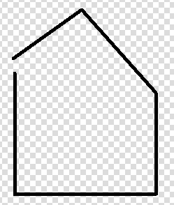
Polylines what are they?
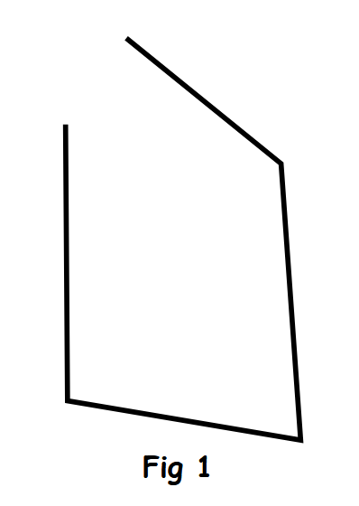
A Polyline is in SVG terms a series of straight lines, like the image shown below, but if you draw a shape like this, using the Vector tools with Pencil2D and then click on it, using the Smudge Tool, Pencil2D will convert it into a curve line. This is done by applying smoothing to the curve. Curve in this context applies to a line, even it it is composed of a series of straight lines.
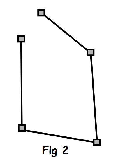
This line is composed of five points, as shown in the second diagram.
When using Pencil2D, vector tools, there is a Polyline tool, but its naming is confusing when looked at from the standpoint of an SVG drawing. True is draws a sequence of straight lines, initially, but is the artist, that’s you attempts to edit them, this is done using the Smudge tool, they are converted in a series of curves.
These curves are created because of the smoothing co-efficient built into the Pencil2D Polyline tool.
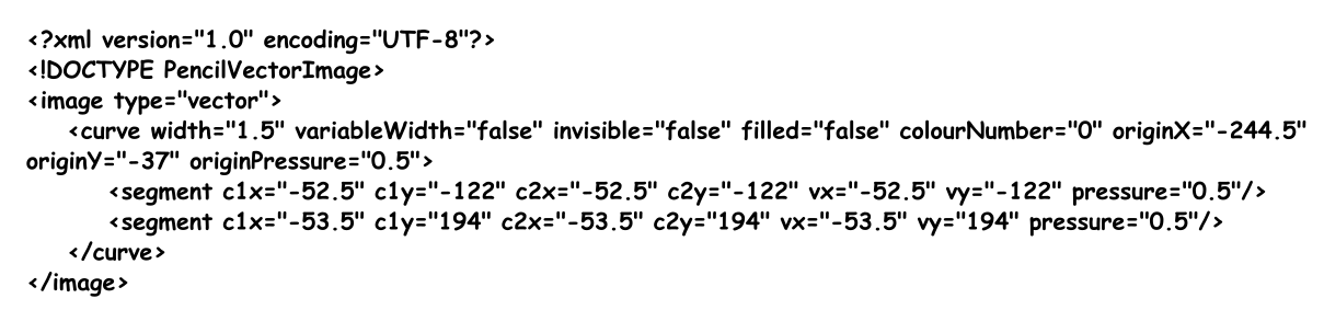
When you examine the initial VEC file for the Polyline, you will notice that there are, two identical segment entries, as shown below.
    <segment c1x="-270.5" c1y="-44.5" c2x="-270.5" c2y="-44.5" vx="-270.5" vy="-44.5" pressure="0.5"/>
    <segment c1x="-270.5" c1y="-44.5" c2x="-270.5" c2y="-44.5" vx="-270.5" vy="-44.5" pressure="0.5"/>
This is because, to terminate the Polyline, it is necessary to double click, the mouse button. After the shape is selected, using the selection tool, shown in black.
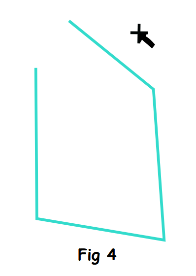
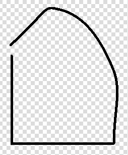
When you select the paint bucket tool
You’ll notice that the paint does not leak out of the gap, between the 2 ends of the line, but instead follows a straight line between the 2 points.
When the line is deselected, using the Smudge tool, the illustration below is the result.
![]()
The SVG file for the above five Polyline shape

The file is contained within <svg and
width=“105mm” - Width of the image height=“148mm” - Height of the image viewBox=“0 0 105 148” - Top right and bottom left points version=“1.1” - SVG Version 1.1 id=“svg5” xmlns="http://www.w3.org/2000/svg” - Links to info on standards used xmlns:svg="http://www.w3.org/2000/svg”>
The lines below define the path, this is svg speak for the line.
style="fill:none;stroke:#000000;stroke-width:1.5;stroke-opacity:1" d="M 36.765955,10.914892 82.148931,47.680851 87.893611,128.68085 19.531915,117.19148 18.957447,36.191491" id="path360" />R style="fill:none;stroke:#000000;stroke-width:1.5;stroke-opacity:1"
This defines the line type, it’s width and the opacity of the line
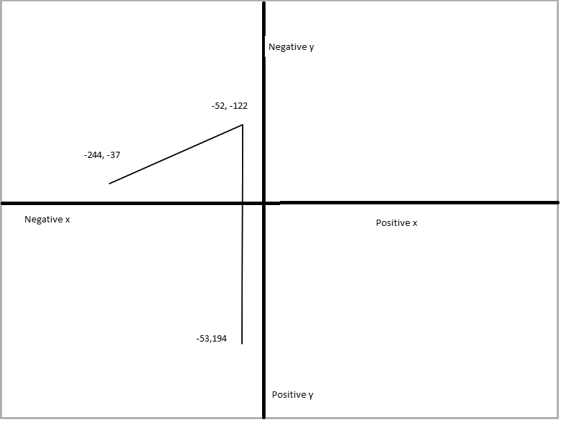
Examining the above file you’ll notice has 5 pairs of numbers, these are the 5 sets of X and Y points, on the line.
d="M 36.765955,10.914892 82.148931,47.680851 87.893611,128.68085 19.531915,117.19148 18.957447,36.191491"
The d= signifies that this is the line data and the M signifies a move command. The X and Y numbers are absolute move distances. The fact that there’s no Z in the line signifies that the 2 ends of the line do not join.
style=“fill:none;stroke:#000000;stroke-width:1.5;stroke-opacity:1”
This line tells us, that the line shape is not filled, the line width is 1.5 and the line Alpha value is 1.
These lines are comments, which tell the reader the format of the file and the program which generated this file.
width=“105mm” height=“148mm” viewBox=“0 0 105 148” version=“1.1”
![]()
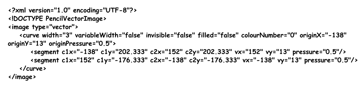
The Pencil2D VEC files, for the above five Polyline shape
This these lines tells the loading program the size of the image and which version of XML is used in this file.

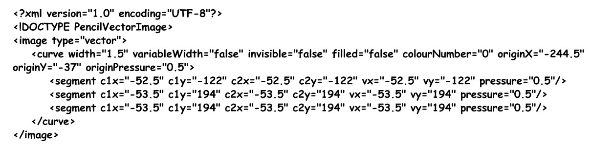
The above file was created using Pencil2D, the repeat of the last segment, is caused by having to terminate the Polyline input, this is achieved by a double click, using the Polyline tool.
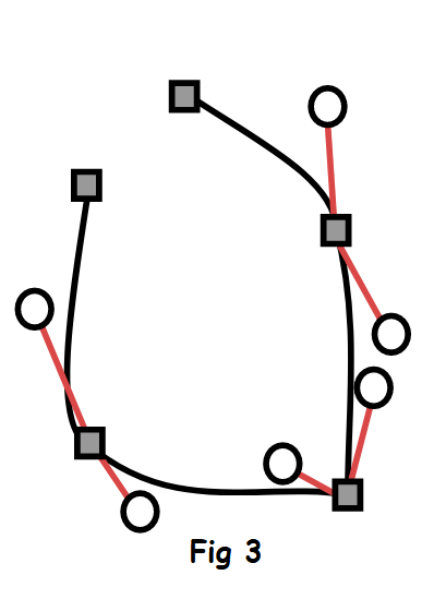
The circles are the curve edit controls attached to the control points. In Pencil2D these cannot be accessed, to allow the curve to be edited. Instead you, as the animator, adjust the position of the control points, as indicated by the grey filled squares, on screen.
Curve edit points exist, for the final point, but you will have noticed, that they have the same values as the X and Y co-ordinates of the final control point.


The above file was produced, by loading the previous file into notepad and manually editing it. You don’t require to repeat the last segment and by it’s nature you can’t repeat the first because there is only originX and originY.
<curve width="4" variableWidth="false" invisible="false" filled="false" colourNumber="0" originX="-266.5" originY="-148.5" originPressure="0.5">
Other information in this line includes line width, in this case 4, variableWidth = false, this is not implemented currently in Pencil2D, filled = false, this becomes filled = true when the shape is filled and originPressure = 0.5. I personally used a mouse, I assume this is to do with using a drawing tablet?
I cannot remember what gave us the idea of using a second copy of the point data, would give us a straight line between the 2 points. But it works, and we are not sure why.
![]()
The Project Aim
The aim of the project is to output a synthetic .PCLX file.
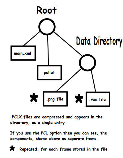
The format of the .PCLX file is shown above. There will be a. VEC file for every drawing in vector format. Once this .PCLX file has been produced, it can then be loaded into Pencil2D or imported as a layer, or layers.
To me, this approach makes no sense. Switching pencil over, to use cairo for import and export of svg files makes more sense to me.
cairo can handle svg, png etc and Qt.
Different Points of View
There has been information about basics of vector images and their manipulation in earlier post, within this topic, because many users of Pencil2D are not fully familiar with vector graphics.
The Pencil2D Point of view
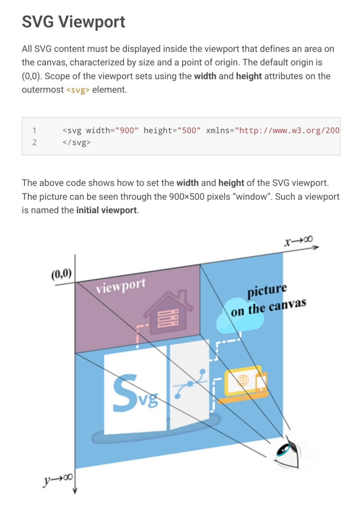
In Pencil2D the 0,0 point, called the origin because this is the point from which all other positions are measured from, is in the center of the screen viewpoint.
The conversion of coordinates from the ISO standard SVG system to the Pencil2D, is going to necessitate moving the 0,0 point. At least the 0,0 point in both cases is at the top, left corner of the positive sector.
How this shape is coded in Pencil2D
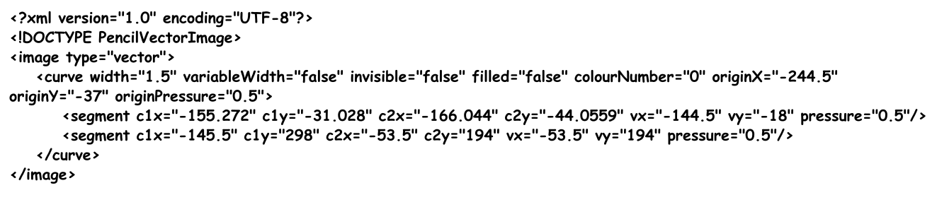
This is a .VEC file, this is stored in the directory, in this case as 002.004.vec. This means that it applies to layer 2, frame 4.
Vec files produced by Pencil2D
The above file, was not generated using Pencil2D, but was converted from an SVG file. Pencil2D would have produced the file below.
You will have noticed that the last 2 segments are identical. This occurs because to end the polyline input, in Pencil2D, requires a double click on the mouse. Sometimes the x and y coordinates will vary slightly, if you moved the mouse between the first and second mouse clicks.
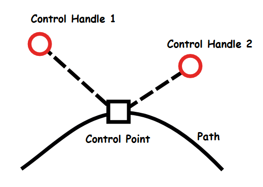
Careful examination of the line below, you will see that both the control handles, are identical to the x,y coordinates of the control point.
This is a quirk of Pencil2D. Thus in the above example the control handles are superimposed on top of the control point.
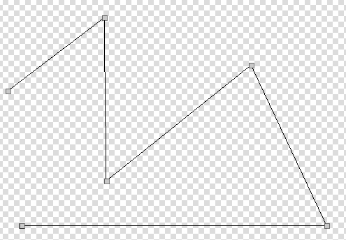
If you load the Pencil2D file 3_Point_line.pclx. 3_Point_Line.pclx (3.7 KB)
When you examine frame 001 on the Vector layer, this has been created as a blank vector frame. Frame 004 is the frame listed above with 3 control points and 2 lines connecting them. Frame 007 is frame 004, but the middle control point has been moved down and left direction. You’ll notice that both lines now include curves, but that the initial section of the first line is still straight. This is due to the control handles being coincident with the control point.
Note that the code, for frame 004, had the second copy of the terminal was absent because the file being operated on was the converted version.
If you now examine frame 012 it will initially look as shown below.
By adding the red line, this is red only to emphasise it’s the added line, and the colour has no effect on how Pencil2D sees it.
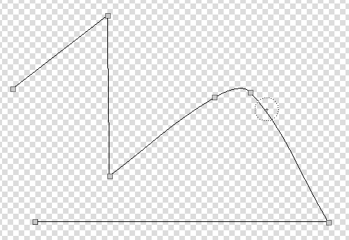
When the red line, is deleted and the line is clicked on using the Smudge tool, there is an extra control point added.
When this is moved on top of the adjacent control point, the line segments either side become straight line.
Have a go, at experimenting with copies of frame 012, to see what changes to the line shape occur.
We are working on the basis, that the images, that are going to be converted from .SVG to .VEC by the convertion program are completed images. That means that we must preserve straight lines when the images are transfered to Pencil2D and subsequently edited, by the animator. Therefor we are proposing to use the repeated points, superimposed to acheive this result!
The images and parts thereof can be moved around the animation stage, rotated, enlarged, reduced, limited graphic sheering and of course colour editing.
We are in effect using the SVG program to do the primary image manipulation and usingPencil2D for presentational functions, including Camera, Sound and production of the final .MP4 file output
What shape is seen, when frame 001 of Mistory_Shape.pclx (1.4 KB)
The listing of the .VEC file is listed below.
Does anyone else, realise, why this .VEC file, frame 002.001.vec plots a curve and why you cannot fill the curve to form a filled shape? I understand what is happening because I understand the mathematics and how Pencil2D converts this .VEC code and the code it contains!
In my experience the problem would still exist, if we used Careo to do the conversion.
The problems being experienced are due to very small, problems, but significant in the data processing sence, in the way that Pencil2D processes vector images.
Efforts to perform the conversion, have brought these to light!
This topic was automatically closed 28 days after the last reply. New replies are no longer allowed.