I produced an .SVG file using Scratch editor. This might seem a strange choice, but it is a well designed editor, which can produce bitmapped and vector images. It only exports images as standard 1.1 version .SVG format. Scratch also has an excellent sound recording and edit suite too. This is well designed, like the drawing software and very easy to use.
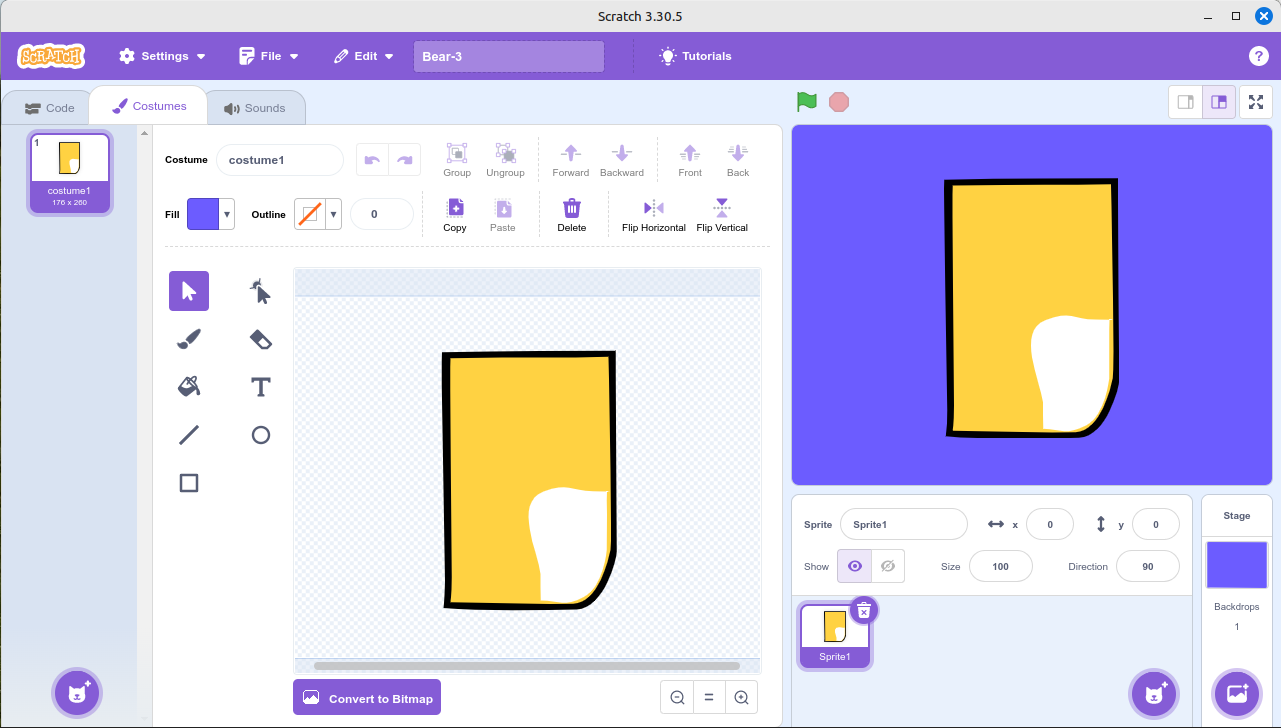
Scratch Screen shot
I’ve chosen using a simplified drawing to illustrate the process. The above illustration shows the drawing of the bears body. I have used more plot points because of the way that the vector display procedures work with Pencil2D.
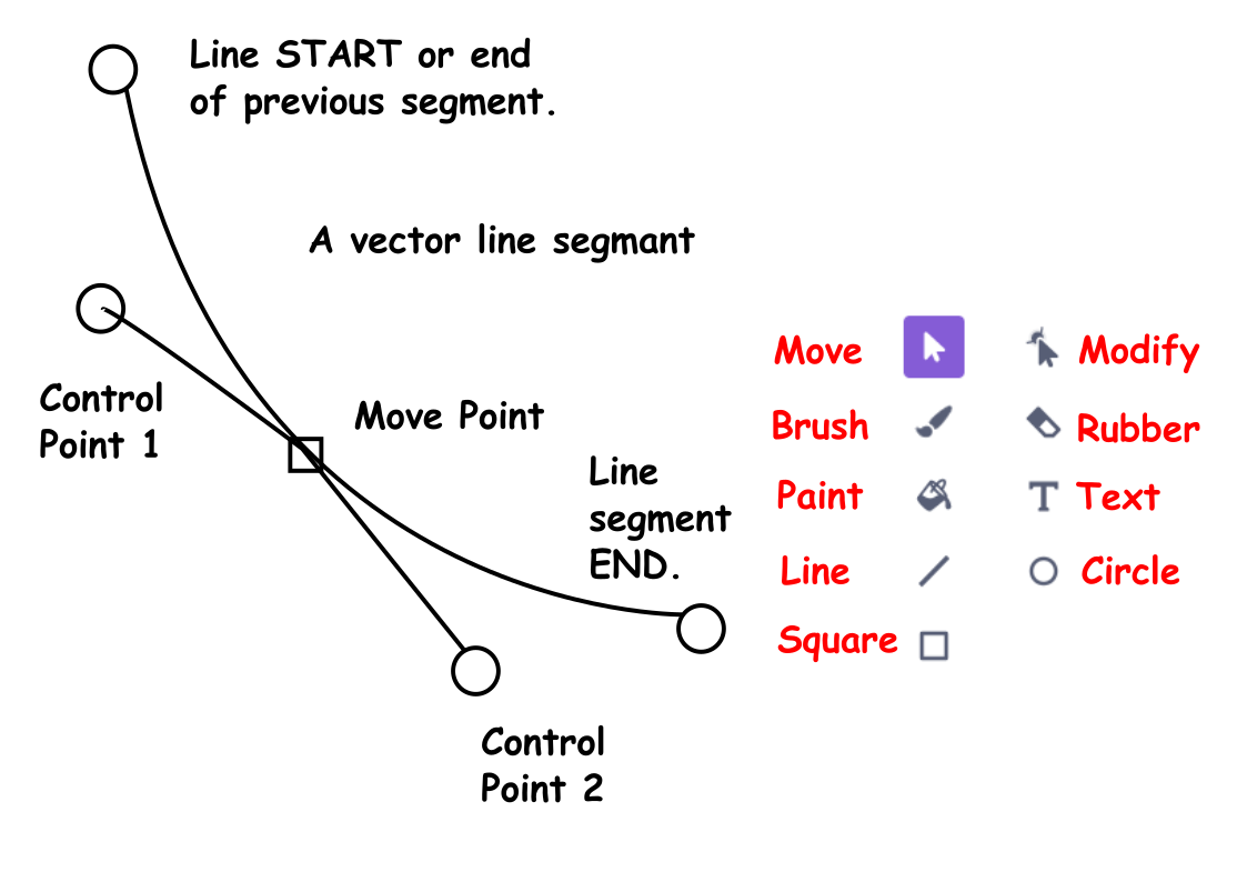
Vector Segment Diagram
All the lines within this example were drawn using the line tool. Initially this is drawn as a straight line. To convert it to a curve, as in the case of the Bear’s belly you click on a point in the middle and then move it as appropriate to create the required curve.
 Actual Line Diagram
Because you going to convert the shape into a shape defined in a .VEC file, next you require to do an action, that may appear to be nonsense. But you’ll see the purpose of this later. Add extra plot points at the ends of the straight lines within the shape. The bottom 2 lines initially are drawn as straight lines and then using the modify tool they are converted into curves. See the illustration below. Then use the select tool and apply a fill colour of the line colour, in this case black.
The repeat the process for the fur colour and the white of the belly. You are probably wondering why we are using a filled shape, instead of a black line. This is because of a small problem with Pencil2D. The program displays the fills in order, from back to front in perspective terms and then on top of these the lines also in order.
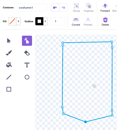
The next stage of the process is to hide the lines and just leave the fills. You will have probably noticed that there are gaps in places between the line and the fills. Select the shapes, making sure that you have selected the belly shapes and then select the outline width and set it to zero. An Orange diagonal line will appear to show you’ve selected the correct option.
Hide Line Operation Curve Line Operation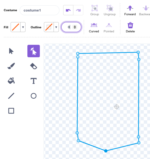
The next operation will probably though you, that’s because it is only necessary because of the way that Pencil2D stores the curves within the .VEC file. The extra data point, at the ends of the straight lines preserve them a straight lines instead of converting them into curves.
This is because Pencil2D uses a Smoothing Coefficient to define and allow you the animator to edit curves.
Now select the whole shape and then apply the curve tool. This converts all lines to curves. The result is that all lines are defined as C1x, C1y, C2x, C2Y and X and Y for the end point.
The listing below is the code within a .VEC file for the outer line as a fill layer.
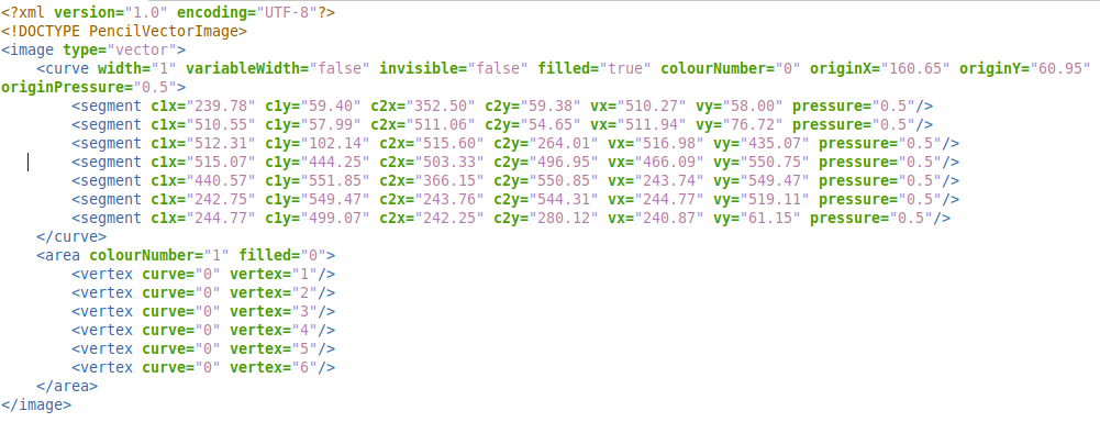
Listing 1
By loading this into Pencil2D by inserting it the data directory it can be displayed and edited by Pencil2D.
The procedure to achieve this manually
Create a new project with a vector layer and a camera layer. Insert a single frame in the vector layer and the save the project as a .PCLX file. Then convert the file type to .ZIP
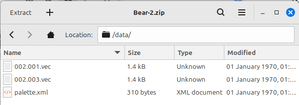
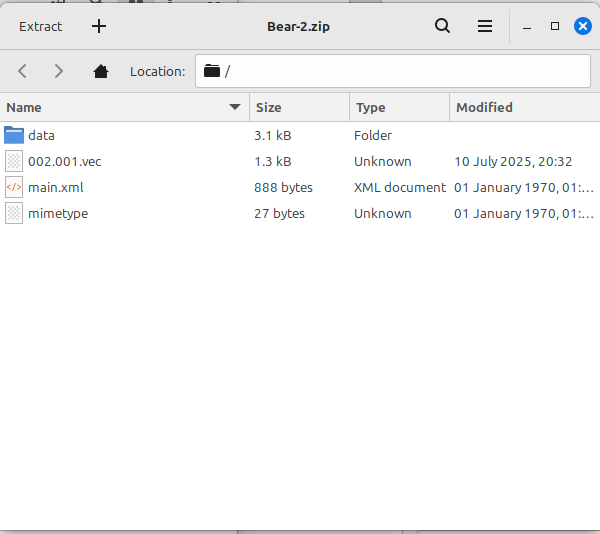
Move Files into .VEC format
Once you done this step, you can cheat because the other 2 steps are effectively a similar shape with minor modifications.
 Bear-2.gif
The file Bear-2.gif show the steps in the process to make the complete file. Because of the way that Pencil2D works the line around the edge must be hidden. The final frame of this animation Bear-2.pclx contains the completed drawing.
Currently the conversion process is carried out using a spreadsheet.
When the transfered image was initially viewed in Pencil2D it like.

But after I’d clicked on each line with the vector Smudge tool it looked like.

The reason is that clicking on lines with the Smudge tool applies the Smoothing Coefficient to the line.
It is planned that when we get the time, that we will convert the process into a program, which will convert .SVG files into .VEC file and it will run on Windows, Linux and MACos systems.
I’ll leave the exploration of the Square and Circle tool to you. They will work, the Square shape will require the extra Move Points to be added and the circle can produce a circle with a little modification.
Interesting note
The points produced by Scratch .SVG mode are sometimes contain 7 decimal place, but we’ve found that 2 decimal places are sufficient.
The animation below is an example of work done using vectors in Pencil2D.