How do I import vector art files to the vector layer?
Pencil2D does not currently support importing any vector formats. You can import entire vector layers from other Pencil2D projects using File > Import > Layers from project file but that’s about it.
As a workaround, you can convert whatever vector files you have to a bitmap format such as png using your preferred vector editor (such as Inkscape), and import that to a bitmap layer. While not unusable, the vector layer in Pencil2D can be difficult for beginners to understand and has several bugs and quirks. Because of this, I recommend using bitmap layers over vector layers unless you have a good reason.
I would like to see basic SVG import and export options added at some point, but to my knowledge no work as been done towards that so far, and substantial improvements to the vector engine would be required before it would even be possible to represent most SVGs faithfully.
You can import vector art from another Pencil2D project, using the import function.
You can draw vector images using the Vector tools within Pencil2D.
You can draw vector images using a vector package and then export them as .PNG files. You still have the advantage of being able to enlarge the images if required.
If you enlarge a bitmapped image more than about 20% the image will pixcelate. But if you have the image in say .SVG format you can reduce export a larger image.
It would make life easier if you could convert .SVG files into .VEC file either within Pencil2D or using an external utility.
I have done this using a text editor successfully, but it requires extensive knowledge of how Pencil2D handles vector images, together with practical knowledge of fixes.
You can of course overdraw the bitmapped images, using the Vector tools within Pencil2D.
I hope this information is useful.
If you want to understand how you can use Pencil2D vector graphics, i provide the project below as an illustration, of what you can achieve.
The project file is also provided for you to examine.
Thanks for answering my question concisely in your first sentence. This makes Pencil 2D a no-go for me.
For me it’s worth the effort of the conversion because a single drawing can be used as a puppet because each component is individually move able, resizeable and you can reshape them too.
Since my work is for cinematographic presentation, you cannot enlarge a bitmapped image without extreme pixcelation occurring. I draw using a Linux desktop computer.
When stop motion talkes about a manual process this involves a spreadsheet, but currently it requires a manual check the results and modify a few commands.
Hopefully when fully debugger the program that will read in an .SVG file and then output a .VEC file.
Despite what some Pencil2D users and group members say, the Vector tools within Pencil2D are problematic they are very usable. Hopefully in time Pencil2D vector tools will be modified to be able to load in .SVG and display them correctly.
I produced an .SVG file using Scratch editor. This might seem a strange choice, but it is a well designed editor, which can produce bitmapped and vector images. It only exports images as standard 1.1 version .SVG format. Scratch also has an excellent sound recording and edit suite too. This is well designed, like the drawing software and very easy to use.
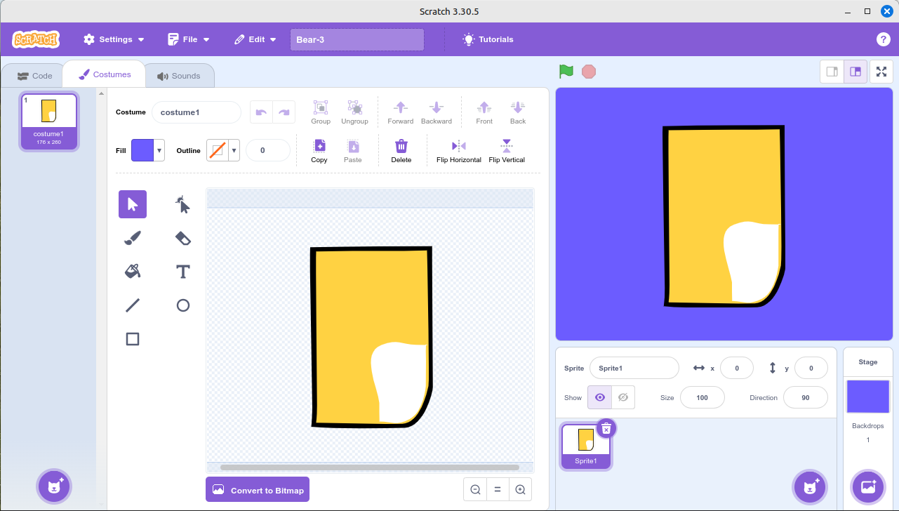
Scratch Screen shot
I’ve chosen using a simplified drawing to illustrate the process. The above illustration shows the drawing of the bears body. I have used more plot points because of the way that the vector display procedures work with Pencil2D.
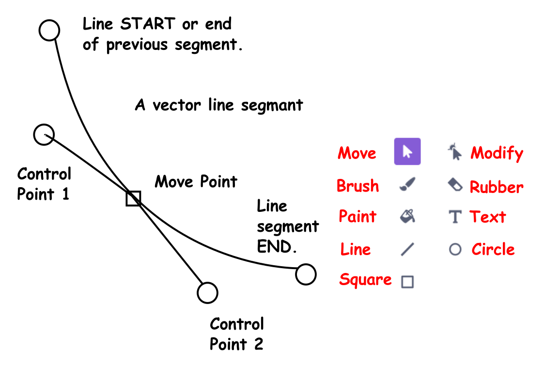
Vector Segment Diagram
All the lines within this example were drawn using the line tool. Initially this is drawn as a straight line. To convert it to a curve, as in the case of the Bear’s belly you click on a point in the middle and then move it as appropriate to create the required curve.
 Actual Line Diagram
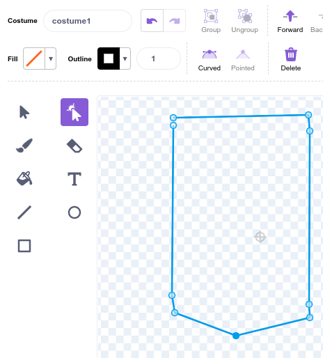
Because you going to convert the shape into a shape defined in a .VEC file, next you require to do an action, that may appear to be nonsense. But you’ll see the purpose of this later. Add extra plot points at the ends of the straight lines within the shape. The bottom 2 lines initially are drawn as straight lines and then using the modify tool they are converted into curves. See the illustration below. Then use the select tool and apply a fill colour of the line colour, in this case black.
The repeat the process for the fur colour and the white of the belly. You are probably wondering why we are using a filled shape, instead of a black line. This is because of a small problem with Pencil2D. The program displays the fills in order, from back to front in perspective terms and then on top of these the lines also in order.
The next stage of the process is to hide the lines and just leave the fills. You will have probably noticed that there are gaps in places between the line and the fills. Select the shapes, making sure that you have selected the belly shapes and then select the outline width and set it to zero. An Orange diagonal line will appear to show you’ve selected the correct option.
Hide Line Operation Curve Line Operation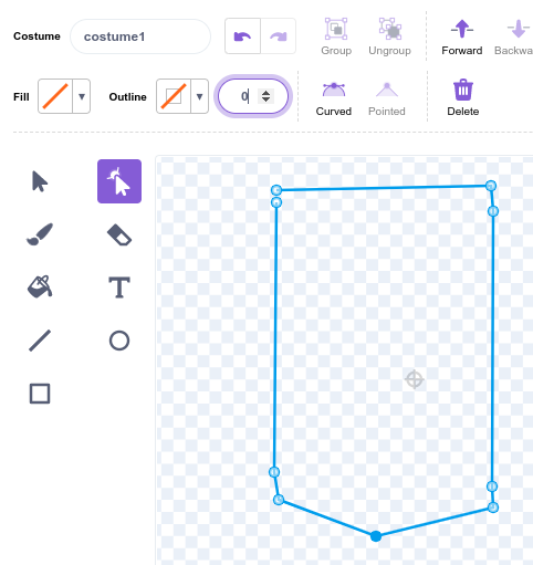
The next operation will probably though you, that’s because it is only necessary because of the way that Pencil2D stores the curves within the .VEC file. The extra data point, at the ends of the straight lines preserve them a straight lines instead of converting them into curves.
This is because Pencil2D uses a Smoothing Coefficient to define and allow you the animator to edit curves.
Now select the whole shape and then apply the curve tool. This converts all lines to curves. The result is that all lines are defined as C1x, C1y, C2x, C2Y and X and Y for the end point.
The listing below is the code within a .VEC file for the outer line as a fill layer.
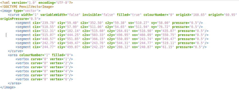
Listing 1
By loading this into Pencil2D by inserting it the data directory it can be displayed and edited by Pencil2D.
The procedure to achieve this manually
Create a new project with a vector layer and a camera layer. Insert a single frame in the vector layer and the save the project as a .PCLX file. Then convert the file type to .ZIP
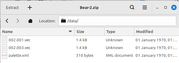
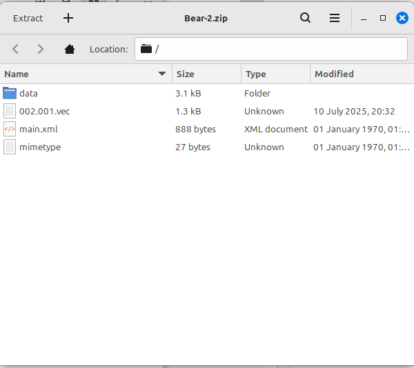
Move Files into .VEC format
Once you done this step, you can cheat because the other 2 steps are effectively a similar shape with minor modifications.
 Bear-2.gif
The file Bear-2.gif show the steps in the process to make the complete file. Because of the way that Pencil2D works the line around the edge must be hidden. The final frame of this animation Bear-2.pclx contains the completed drawing.
Currently the conversion process is carried out using a spreadsheet.
When the transfered image was initially viewed in Pencil2D it like.

But after I’d clicked on each line with the vector Smudge tool it looked like.

The reason is that clicking on lines with the Smudge tool applies the Smoothing Coefficient to the line.
It is planned that when we get the time, that we will convert the process into a program, which will convert .SVG files into .VEC file and it will run on Windows, Linux and MACos systems.
I’ll leave the exploration of the Square and Circle tool to you. They will work, the Square shape will require the extra Move Points to be added and the circle can produce a circle with a little modification.
Interesting note
The points produced by Scratch .SVG mode are sometimes contain 7 decimal place, but we’ve found that 2 decimal places are sufficient.
The animation below is an example of work done using vectors in Pencil2D.
Between the initial posting of my ‘Blue Movie’, a figure of speech on this channel, I realised I’d made a minor error.
Below is the updated animation, see if you can spot my error in the original animation.
Below us the .PCLX file, have a look at it’s contents. The correction didn’t require extra or modified drawings. I simply picked up the legs and moved them to the new positions.
Bear_Draw-7.pclx (1.0 MB)
Incidentally using Scratch vector drawing tools gives me access to vector text, without having to draw the individual letters from scratch, get the pun!
The letters in the above file are bitmapped on a bitmap layer.
All the screen images have been obtained using Screen Grab with Linux
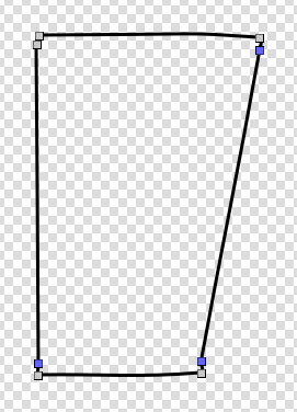
Drawing straight line, which are to be used within a Pencil2D
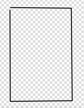
This is how the line initially looks, it has a single control point at each corner, except between the start and finish of the line.
At this point the Smoothing Constant has not be applied to the line.
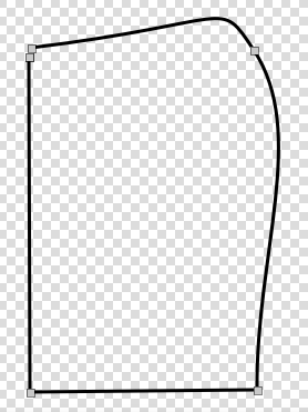
To apply the Smoothing Coefficient to the line, select the Smudge Tool and click outside the drawing and the illustration show below results.
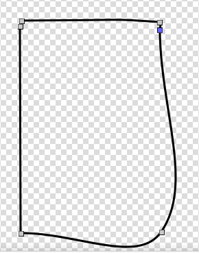
A extra control point is then added by drawing a line which crosses the rectangle? And then move nearer the existing control point. The curve changes shape.
After repeating the same process as the previous process, this is how the shape of the rectangle appears. I usually add an extra control point on the other point at the bottom edge of the Rectangle. This is a belt and bracers process.
There are of course 2 points at the start / finish point of the Rectangle.
If you place the control points near to each other then you can pick them up together and move them.
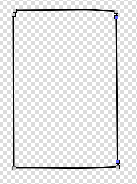
The technique allows you the animator to adjust the shape of the transition from a curve to a angular transition, like the corners of the rectangle example.
Drawing curves using Pencil2D to draw or display
This is the process to draw curves using the line draw tool within Pencil2D or using the line tool within a vector package like Scratch.
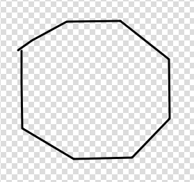
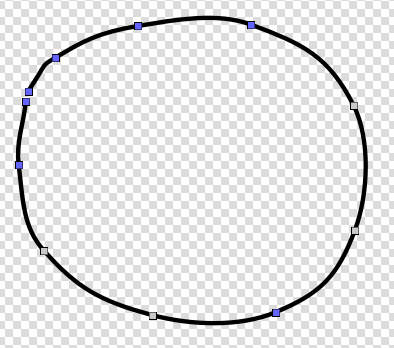
Within a vector package like Scratch there’s another option this is you can use the circle tool and then add extra control points within the 2nd and 3rd sectors and 2 extra points within the 1st and 4th sector.
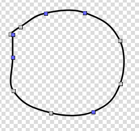
In all these examples I’ve started drawing from the top Left corner.
Adding fills to shapes
To apply a fill to a defined shape using the Cutout Tool to make this selection you must enclose the complete shape.
If you require to change the line colour select a colour and using the Cutout Tool, but only enclose part of the shape, say the left hand end The using the Paint Bucket too click outside the shape.
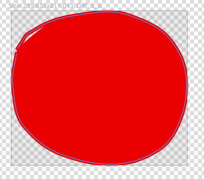
You’ll notice there’s a slight gap between the fill and the line.
The 2 illustrations above & below, the images were screen grabbed whilst the shapes were selected!
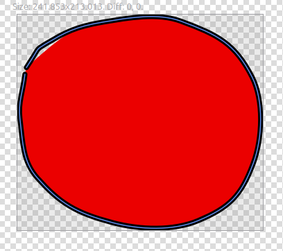
In the case of simple curves like this one drawn directly using the Pencil2D drawing tools, the points can be adjusted to remove the gap.
But there’s another problem which occurs if you draw using Pencil2D tools or import the image into Pencil2D.
In theory, there shouldn’t be a gap between the fill and the line, but this happens because the modification of the line shape and the fill shape isn’t affected by the Smoothing Coefficient in the same way.
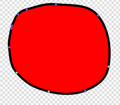
Concepts re Vector Drawing Tools
The edge of the fill is more easy to adjust to get a smooth curve. The line has a problem with the 1st 2nd and the last segments of the curve not being smoothed the same ways as all the other segments.
This happens because the vector space hold the information in a image stack. This in principal works the same as a stack of books. But using Pencil2D the fills are displayed in order, but then the lines are drawn in order.
If your drawing an image that requires 3 lines which are then filled, with colours. These are displayed as Fill, Fill, Fill then Line, Line,Line. This doesn’t work to produce a meaningful result. This is why iii the example of the Bear’s body the lines around the flat fills are produced using another fill shape.
Some Minor Pitfalls when suing Pencil2D Vectors
Any line that you draw using Pencil2D Vectors must have at least 3 control points, these are boxes that appear at the end of strokes, when you click on the line using the Smudge Tool. If you have lines with 2 of the points, then you’ll have serious problems editing them! Where we found this out was drawing letter, in particular lower case i’s!
A Silver Lining, with Pencil2D
There is another advantage, a silver lining, Pencil2D doesn’t allow you to vary the line width, but using 2 fill layers you can achieve the variable line width.
Tools missing in the Pencil2D Vector Toolset
There’s no Rectangle of circle tool. Also most vector packages including the Scratch Vector editor have text tool. But fr now you’ll have to using a bitmapped text and import it into a bitmapped layer. Myself and collogues have drawn title text using the vector tools. Once you done this a few times this task is not so daunting as you imagine.
There’s no tool to move drawings from the background, that’s the bottom of the vector image stack to the foreground nearer the top of the image stack.
Unlike many bitmapped and vector packages you can’t cut a part of the image and then paste it into another frame unfortunately Pencil2D pastes the entire image.
Why we use Pencil2D 4 Vector Animation
My Colleagues and I have a series of work around which enable us to produce production work, using the Pencil2D vector toolset.
Once you have selected the control points in a frame, these are selected in all the frames for equivalent drawing components. There is currently no way of deselecting this option. But there’s a simple work around, save your project file, leave Pencil2D, then return and reload your project file.
We use Pencil2D vector tools because they perform the job and are a stable platform. Pencil2D also has good sound layer and excellent camera facilities.
But you can produce excellent work, using Pencil2D Vector Drawing Tools!
I hope this information is useful to those wondering about how Pencil2D Vector graphics work!
WARNING
No line drawn, using Pencil2D vector tools should have less than 3 points. This is because you won’t be able to select such a line within the Vector Toolset.
Also it’s possible, to draw a line from outside the Pencil2D vector space. Such lines cannot be edited or deleted. The only solution is to delete the whole vector frame which contains them!